Sunday, April 24, 2016

Deliverable III: Process Optimization


Dome Optimization:

Figure 1: First production of injection molded dome with clear defects.

Figure 2: Left to right: Process of optimization and noticeable disappearance of hole.

Figure 3: Optimized injection molded dome with no defects.

Process plan for Dome Cavity mold

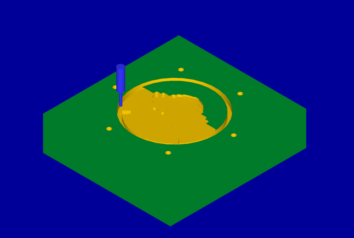
*Positive vacuum vent holes were created on the cavity mold to prevent the defects seen in Figure 1 ie. holes. This was done after trying regular vacuum holes to no avail. Large holes were drilled on the back face of the mold then collapsed, after this the actual vacuum holes were drilled with the small 0.025" drill bit.
**Step 7 was repeated with a 60 degree rotation to create three more small runners. 

Process plan for Dome Core mold  

*Step 5 was remachined in post operation with same 3/32" flat end mill bit. This was done to ensure better snapfit, and the parameters were calculated by measuring final shrinkage factors.

To optimize the dome, the outer  
Set Up Sheet for Injection Molding of Dome (Optimized Parameters)


Injection Hold
Injection Hold Pressure Profile: P7-P16
500
500
500
500
500
500
500
500
500
500
Injection Hold Time
8.0 s
Cooling Time
10.0 s
Set Screw Feed Stroke (Shot Size)
1.7 in
Injection Boost
Injection Speed Profile: V12-V21

3.0
4.0
5.0
4.0
3.0
2.0
1.0
0.4
0.2
0.1
Injection Boost Pressure
1000 Psi
Screw Feeding
Screw Feed Delay Time
2.0 s
Ejector
Ejector Counter
2
1/8” Ejectors Pins Length
5.095
¼” Ejector Pin Length
#2
To mitigate the visible defects (Figure 1), the injection molding parameters were increased to their max in order to cause the mold to burn. This allowed us to determine the locations of the defects and machine the vacuum holes. The positive vacuum holes effectively removed the defects as seen in Figure 2. We then changed injection molding parameters to optimize the part, and the final parameters are seen in the set up sheet above. The final optimized part is seen in Figure 3.

Map Optimization:

The map was originally too large to snap into the body shell. To fix this, we remade the cavity mold to have a smaller OD in order to allow for the snap fit with the measured shrinkage tolerances taken into account. The injection molding parameters were optimized, and can be seen in the set up sheet below.

Injection Hold
Injection Hold Pressure Profile: P7-P16
1000
1000
1000
1000
1000
1000
1000
1000
1000
1000
Injection Hold Time
8.0 s
Cooling Time
25.0 s
Set Screw Feed Stroke (Shot Size)
2.2 in
Injection Boost
Injection Speed Profile: V12-V21

4.5
5.0
5.5
5.0
4.0
4.0
4.0
3.0
2.0
1.5
Injection Boost Pressure
1500 Psi
Screw Feeding
Screw Feed Delay Time
2.0 s
Ejector
Ejector Counter
2
1/8” Ejectors Pins Length
5.570
¼” Ejector Pin Length
#2
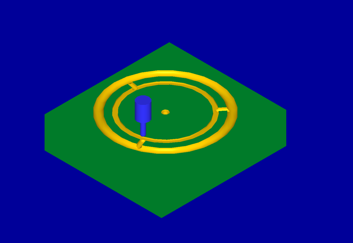
Optimized injection molded Hack Map. 

Body Shell Optimization:

There was only one iteration for the mold that makes the body of the yo-yo. Several body shells were injection molded using this mold. We inspected all of them and saw that they were consistently without blemishes of any sort (short shots, flashes, etc). The snap fits of the hack map and the dome were individually modified to fir the snap fits set in the body shell. Therefore, the original settings resulted in optimal body shells for our yo-yo.


Injection Hold
Injection Hold Pressure Profile: P7-P16
400
400
400
400
400
400
400
400
400
400
Injection Hold Time
8.0 s
Cooling Time
20.0 s
Set Screw Feed Stroke (Shot Size)
2.2 in
Injection Boost
Injection Speed Profile: V12-V21

3.5
4.0
4.5
4.0
3.0
3.0
3.0
2.0
1.0
0.5
Injection Boost Pressure
801 Psi
Intrusion Speed
100 in/s
Screw Feeding
Screw Feed Delay Time
2.0 s
Ejector
Ejector Counter
2
1/8” Ejectors Pins Length
5.460
¼” Ejector Pin Length
#2
Optimized injection molded Hack Map/Dome Shell.

Thermoform Optimization:

Optimized thermoformed Dome Cover.

The production time of the thermoformed Dome Cover was minimized reducing the form time by 5 seconds and increasing both the top oven and bottom oven temperatures by 25 degrees fahrenheit.  


Sunday, April 3, 2016

Deliverable II: Injection Molding and Process Optimization

The most interesting injection molded part is the ‘Dome’ Face of our design. It features an image of the great dome on which we will display our hacks, with the columns cleverly substituted for the MIT modern logo. 
The part is designed for maximum machinable resolution by using 1/32 radius.  Each level is separated by 20 thousandths to give a strong illusion of depth while maintaining machinability.  A five degree draft was utilized to make the large vertical surface area stick less in the mold and eject more easily.  The part was also scaled up by 2% due to comparisons of major part geometries (maximum thickness and diameter) with injection molding shrinkage blanks provided in the Laboratory for Manufacturing Productivity.  

Solidworks design of the Dome Face to be injection molded


Core and cavity molds
Upon entering MasterCam x6, our Computer-Aided-Machining package, we decided to utilize a runner on this mold due to concerns the long, thin, outer ring would not fill properly.  


The core manufacturing process utilized a 2” face mill to face the part and ⅛” end mills to bore the mold, with ½” and ¼” spherical bits to mill the runner. The cavity utilized a 2”, ¼”, 3/32”, and 1/16” flat end mills in decreasing order to quickly remove material while constantly increasing resolution. A .12” peck drill was used to create ejection pin holes that align with the runner on the cavity. This way we would not deform the part itself upon ejection.  

Finished injection molded of the Dome Face 
The finished part shows significant issues with short shot pockets and vacuum inclusions. The cooling of the stairs on this first part created vacuum inclusions which did not appear on later parts, leading us to believe that there was simply material left on the surface. There are two pockets created where plastic had difficulty flowing consistently across our test parts.  We will consider adding air holes.

Moreover, we also injection molded the body of our Yoyo in order to ensure that the two pieces properly fit together, which they did.

Finished injection molded for the Body of our Yoyo
Assembly of injection molded Dome Face and Body
Below are the manufacturing process plans for both sides of the Dome Face and Body molds. You can find the full list here

Manufacturing process plan for Dome Face Core

Manufacturing process plan for Dome Face Cavity

Manufacturing process plan for Body Core

Manufacturing process plan for Body Cavity

The total time required to machine all of our molds is 3 hours and 59 minutes. This did go over because of the time required to switch the tools on the machine. We also noticed periods of no cutting occurring during the machining process. We hope to remove this defect and thus reduce the machining time by approximately half an hour.


Below are images of our other four molds: two for injection molding and two for thermoforming.

Body


Dome Cover Die


Hack Map 


Hack Ring Die