The most interesting injection molded part is the ‘Dome’ Face of our design. It features an image of the great dome on which we will display our hacks, with the columns cleverly substituted for the MIT modern logo.
The part is designed for maximum machinable resolution by using 1/32 radius. Each level is separated by 20 thousandths to give a strong illusion of depth while maintaining machinability. A five degree draft was utilized to make the large vertical surface area stick less in the mold and eject more easily. The part was also scaled up by 2% due to comparisons of major part geometries (maximum thickness and diameter) with injection molding shrinkage blanks provided in the Laboratory for Manufacturing Productivity.
 |
| Solidworks design of the Dome Face to be injection molded |


 |
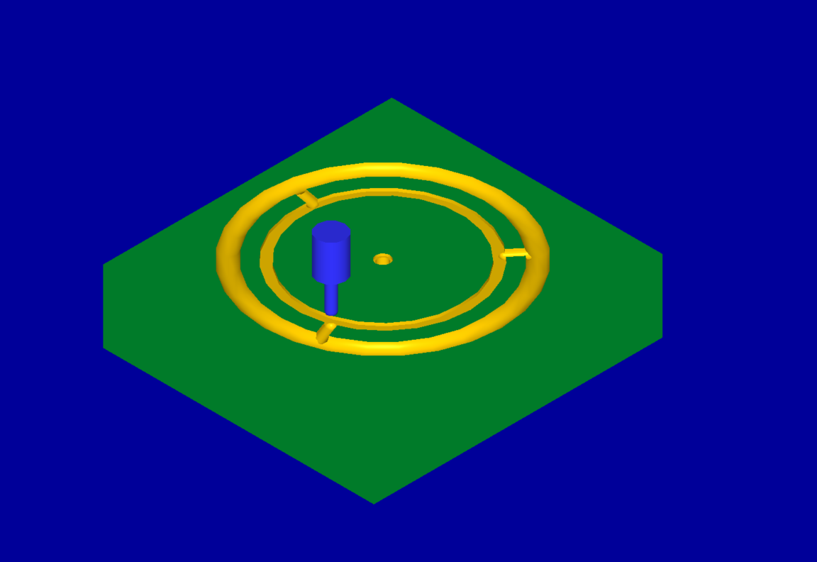
| Core and cavity molds |
Upon entering MasterCam x6, our Computer-Aided-Machining package, we decided to utilize a runner on this mold due to concerns the long, thin, outer ring would not fill properly.
The core manufacturing process utilized a 2” face mill to face the part and ⅛” end mills to bore the mold, with ½” and ¼” spherical bits to mill the runner. The cavity utilized a 2”, ¼”, 3/32”, and 1/16” flat end mills in decreasing order to quickly remove material while constantly increasing resolution. A .12” peck drill was used to create ejection pin holes that align with the runner on the cavity. This way we would not deform the part itself upon ejection.
 |
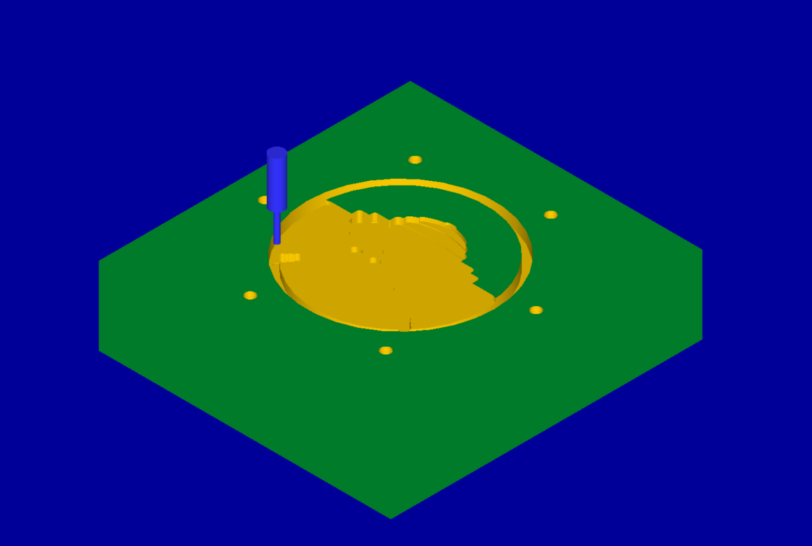
| Finished injection molded of the Dome Face |
Moreover, we also injection molded the body of our Yoyo in order to ensure that the two pieces properly fit together, which they did.
 |
| Finished injection molded for the Body of our Yoyo |
 |
| Assembly of injection molded Dome Face and Body |
 |
| Manufacturing process plan for Dome Face Core |
 |
| Manufacturing process plan for Dome Face Cavity |
 |
| Manufacturing process plan for Body Core |
 |
| Manufacturing process plan for Body Cavity |
The total time required to machine all of our molds is 3 hours and 59 minutes. This did go over because of the time required to switch the tools on the machine. We also noticed periods of no cutting occurring during the machining process. We hope to remove this defect and thus reduce the machining time by approximately half an hour.

Below are images of our other four molds: two for injection molding and two for thermoforming.
Body


Dome Cover Die


Hack Map


Hack Ring Die


No comments:
Post a Comment